-40%
DCC Motor Decoder - Turn any DC loco into DCC .00 AUD
$ 6.43
- Description
- Size Guide
Description
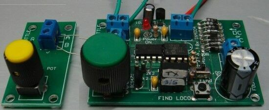
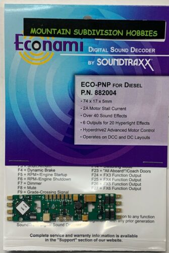
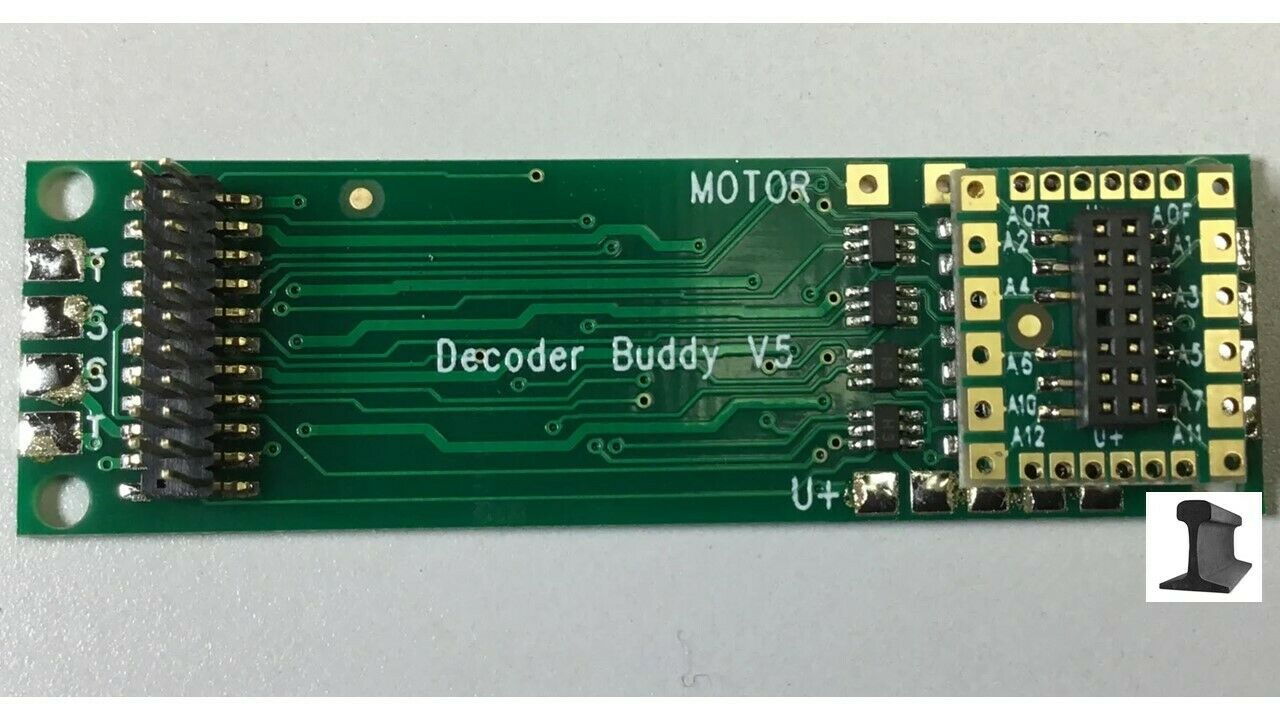
Turn a DC Loco into a DCC loco with this universal Motor Decoder for .00DCC Decoder for Motor - shown in images 1, 2 and 3 above.
This is a 1amp decoder NOT 500mA as per most of the small decoders advertised.
The output has 3amp FETs so the output stays as "cold as a frog." And the diodes are 2 amp - not 1 amp as in all the tiny decoders.
Lots of these decoders have been sold and you can create a new DCC section on your layout using your own controller or our Dual controller. Our Dual Controller is very easy to set-up and can be used by your friends, children or as test set-up as no programming is required and both Motor Decoders can be used at the same time. It is much easier to use than all the hand-held controllers on the market and puts new life into two of your DC locos. The Decoder comes on two PC boards that are joined by 6 insulated wires to make it easy to fit the boards into small spaces.
All you have to do is cut the two wires to the motor and insert the module.
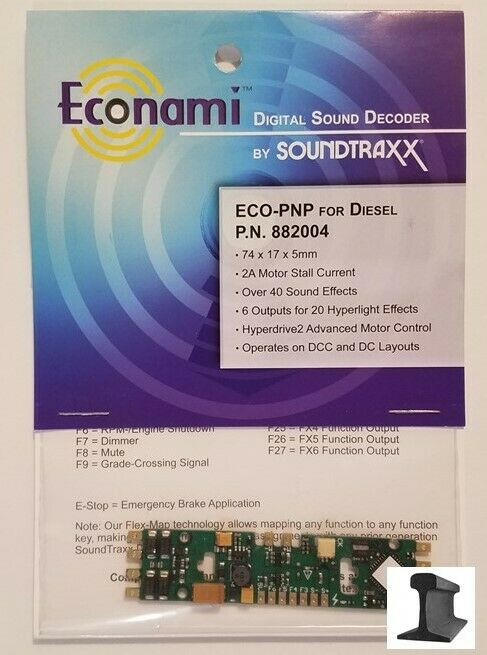
The fourth image above shows 2 screened leads (equal to 4 wires) from the loco. These 4 go to the input and output of the module.
The module is fitted in the tender if there is insufficient room inside the loco.
The latest version of the decoder uses two half PCB's connected with fine insulated wires so the board can be fitted easily.
This is the cheapest way to get into DCC control.
For further information, contact Colin Mitchell at Talking Electronics.com or email: talking at tpg.com.au
This DCC Motor Decoder will NOT work with Hornby controllers as Hornby uses a different set of digital codes that are not compatible with the normal (accepted) DCC coding system.
Almost any 3-pole DC motor will work with the decoder, including pancake motors and "core-less motors."
INSTRUCTIONS FOR INSTALLING THE MOTOR DECODER:
When you receive your Motor Decoder, it will have an address such as 3 or 5 or 31, 32, 33, 34, 35, 36
The Decoder comes with leads and alligator clips so you can test everything before installation. The leads near the 4 power diodes clip onto the two rails of your DCC layout. The other two leads clip to your motor.
DUAL DCC CONTROLLER - see Talking Elecgtronics website for images of this module.
The Dual DCC controller will control 2 locos at the same time and is an ideal way to create a DCC set-up. And the cost is just .00 AUD posted worldwide.
It can also be used with 2 DCC locos that you have converted from DC to DCC via two Motor Decoders shown above.
The only additional item you require is a 12v DC supply from a SLA battery or a 15.9v supply from 4 Li-Ion cells (18650) or a 15v AC supply from a train transformer.
Full details details are provided on Talking Electronics.com website
This is the cheapest way to get into DCC control.
The two DCC Motor Decoders are available from Talking Electronics.com so you can convert 2 DC locos to DCC, and operate them on the same track.
For further information, contact Colin Mitchell at Talking Electronics.com or email: talking at tpg.com.au
POWER SUPPLY
You will need a 15v AC or DC supply.
15v DC is the best as it can be connected to the DUAL DCC CONTROLLER module via the 12v DC screw terminals.
This will give 15v to the chip and produce about 14v AC waveform from the output of the chip.
The image above shows a 15v 2 amp DC plug Pack (wall wart). This is what you need.
There are many types available on eBay for .00 posted. (I do not sell them)
Some are for 240v and some for 110v to 240v AC input.
Make sure you get one with the plug that suits your power outlet.
The output must be 15v DC at 2 Amp.
SETTING UP THE DUAL DCC CONTROLLER
Place a NEW 1 metre length of track next to your layout.
Place the DC loco on the new track.
Connect the other two leads to this new track.
Now set your controller to address 3 to 36 and use the throttle knob to drive the loco forward and reverse.
Make sure you are happy with the performance.
Now open the loco and cut the two wires to the motor.
Make sure no wires are connected to the chassis.
Now connect the two wires next to the 4 power diodes on the Motor Decoder to the DCC track. Connect the other 2 wires and alligator clips to the motor.
Place the "bogey" (motor and wheels) on the DCC track and carefully drive the loco back and forth very slowly.
You have now proven the Motor Decoder will work correctly when fitted inside the loco or in a coal tender or any suitable carriage behind the loco.
If you have any problem: email Colin Mitchell talking at tpg.com.au
You now have a DCC set-up.


